
SA301 12V DC 3 Wire
SA301 is a three-wire, 12V DC connection for motorized valve actuators.
Before You Begin
Power Supply Requirement: Prepare a 12V DC power supply, preferably rated at 1.5A or higher.
Always refer to the actuator's label or datasheet to confirm its supply and current requirements, as these may vary between models.
Disconnect power before making or changing connections.
Wiring Diagram
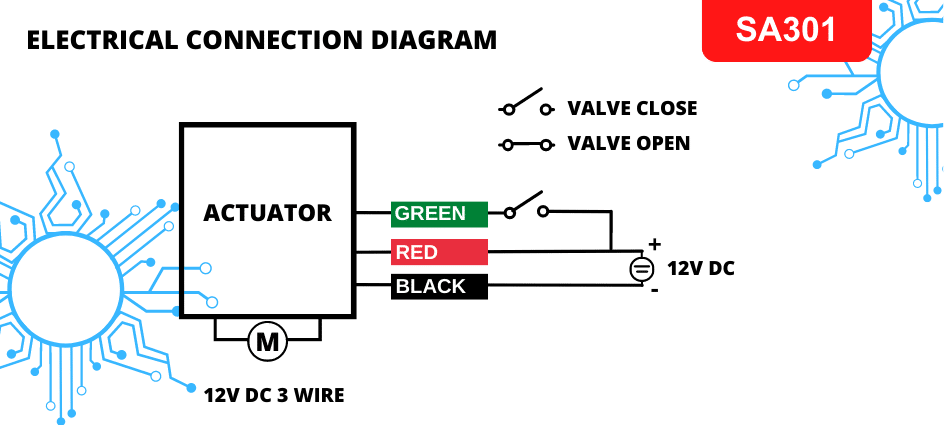
Wire Connections
The SA301 actuator has three colored wires:
- Red Wire (Power +12V DC): Connect to the positive terminal of the power supply.
- Black Wire (Power Ground): Connect to the negative terminal (0V/GND) of the power supply.
- Green Wire (Open Command Signal): Connect to +12V DC when the valve needs to be opened.
Keep red and black connected to the 12V DC supply during normal operation.
How It Works
- The valve opens when green is connected to +12V DC.
- According to the supplied operating instructions, disconnecting green stops opening and the valve holds its last position.
- Use a PLC, relay, float switch, or manual switch to control green.
Stay-put operation: The actuator holds its current position if power fails.
Diagram clarification needed: The diagram labels a disconnected green wire as “valve close,” which conflicts with the supplied hold-position instructions. Confirm the correct closing and stop behavior for your actuator before testing or commissioning.
Power Consumption
- Idle, valve closed: Approximately 0mA.
- Idle, valve open: Approximately 20mA.
- During movement: Up to 1.5A, depending on the actuator specifications.
Current demand is highest during movement. Idle current may be minimal rather than zero; check the actuator's specifications.
Quick Test
After confirming the operating behavior for your actuator:
- With the supply switched off, connect red to +12V DC and black to GND.
- Apply power, then connect green to +12V DC to check opening.
- Verify the response when green is disconnected against the confirmed model instructions.
- Switch off the supply before changing or disconnecting any wiring.
Notes & Tips
- Keep red and black connected during normal operation.
- Apply only the specified 12V DC signal to green.
- Do not reverse polarity; this can damage the actuator.
- Removing power holds position; it should not be described as a reset without confirmation from the actuator's documentation.